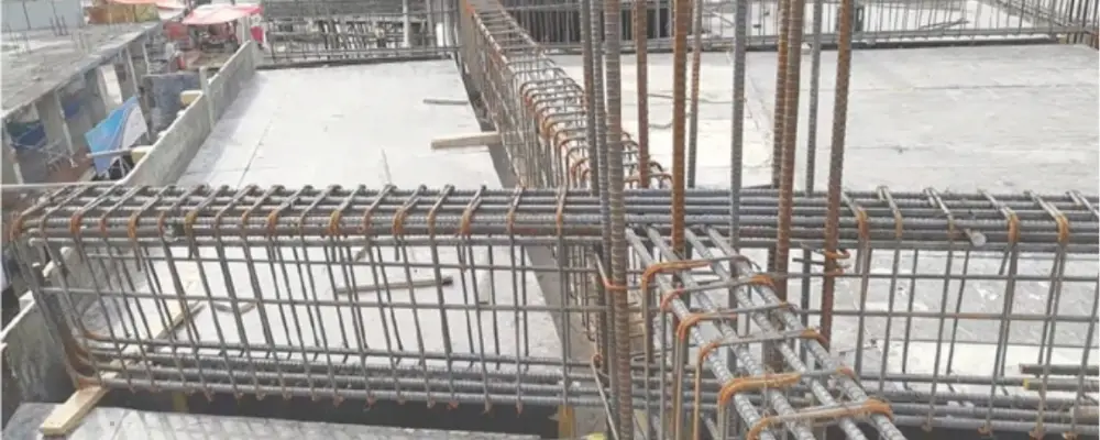
For concrete projects to be structurally strong, long-lasting, and economical, the detailing of reinforcements in beams and slabs is essential. Key elements, including cover depth, bar lengths, curtailment, and the quantity and diameter of reinforcements, must all be specified for proper reinforcement detailing.
For simply supported beams and slabs, shear forces occur nearer to the supports, requiring shear reinforcements in those areas, while the maximum bending moment occurs at the centre of the span, requiring tension reinforcement there. Bending reinforcements can be restricted or bent upwards to act as shear reinforcements, balancing cost-effectiveness and strength to maximise material use.
Fundamentals of Reinforcement Detailing
The maximum bending moment in a normal concrete slab or beam supported simply occurs close to the centre of the span, and the shear force is concentrated at a distance of d/2 from the support face, where d is the effective depth of slab or beam.
This indicates that the centre of the span, where bending moments are greatest, requires more bending reinforcement than the supports. On the other hand, strengthening is necessary for the supports to successfully withstand shear stresses.
Therefore, tension reinforcement does not need to be applied over the entire structure. By bending the bars upward at predetermined spots, up to 50% of the reinforcement can be restricted at suitable sites and diverted for use as shear reinforcement.
Materials Used for Reinforcement
The primary features and uses of each reinforcement material are listed in the table below. You can select the one that works best for your building project.
| S.No | Feature | TMT Steel Bars | Concrete | Epoxy-Coated Carbon Steel | Wire Mesh | Geotextiles |
| 1 | Material | Steel | Base material | Epoxy-coated carbon steel | Steel wires | Synthetic fibers (Polyester, Polypropylene) |
| 2 | Strength | Very High | Moderate to high (compressive) | Moderate | Moderate | Low |
| 3 | Stiffness | Moderate | High | Moderate | Moderate | Low |
| 4 | Corrosion Resistance | High | Moderate (susceptible in harsh environments) | Good | Low | NA |
| 5 | Cost | Moderate | Low | Moderate | Low | Low |
| 6 | Weight | Heavy | Heavy | Moderate | Light | Light |
| 7 | Flexibility | High | NA | Moderate | Low | NA |
| 8 | Applications | General construction (buildings, bridges, pavements) | Used as the significant building material in various construction applications | Moderate corrosive environments, improved bond | slabs, walls, and pavements | Soil reinforcement, filtration, drainage |
Detailing of Reinforcements in Beams
- General Standards and Guidelines
Reinforcement detailing must comply with relevant codes such as BS 8110 Part 1 and IS 456:2000. These standards ensure the beam is safe, durable, and efficient. - Key Rules for Reinforcement Detailing
Tension and Compression Reinforcement:
- Rectangular sections with yield strength fy=460N/mm² require a minimum tension reinforcement of 100As/Ac=0.13.
- Minimum compression reinforcement is required when necessary for ultimate limit states, set at 100As/Ac=0.4.
- The maximum amount of reinforcement, either compression or tension, cannot be more than 4% of the cross-sectional area of the beam.
Shear Reinforcement (Links or Stirrups):
- Links must be at least 6 mm in diameter or at least 25% the size of the largest compression bar, whichever is larger.
- The maximum link spacing is twelve times the diameter of the smallest compression bar.
- In compression zones, no bar may be farther than 150 mm from a confined bar.
Beam Side Reinforcement:
- For beams deeper than 750 mm, provide reinforcement covering 2/3 of the height from the tension face. There should be no more than 250 mm between them.
- Curtailment of Reinforcement
Top Reinforcement:
- From the support, supply 100% of the necessary hogging steel up to 0.15 times the effective span and 60% more than this up to 0.25 times the span.
- Use 20% of the required tension steel as hanger bars beyond this point.
Bottom Reinforcement:
- Curtail or bend upward as required to serve as shear reinforcement in areas of low bending moments.
- Anchorage Details
- Tension anchorage length is critical at supports and must be calculated based on restraining bar locations.
- Use U-bars or lower construction joints at beam-column intersections to maintain required anchorage lengths.
- Beam-to-Beam Connections
- Reinforce areas where one beam supports another to handle vertical forces. Determine the area of reinforcement needed to successfully withstand axial loads.
- Practical Tips for Implementation
- Use bending moment diagrams to adjust reinforcement placement as per load variations.
- Follow detailing rules strictly for effective load transfer and cost efficiency.
- Make sure that bars in tension zones are spaced clearly apart; no bar should be more than 150 mm from a vertical link leg.
By adhering to these comprehensive guidelines, reinforcement detailing for beams can achieve structural stability and cost optimisation while maintaining compliance with design standards.
Detailing of Reinforcements in Slabs
- Adhere to Relevant Codes and Standards
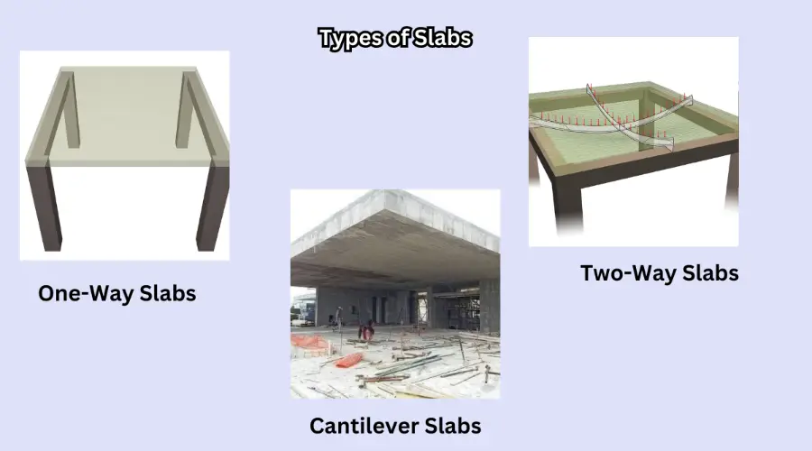
Follow established guidelines such as BS 8110 or Eurocode 2 for slab reinforcement detailing to ensure safety, durability, and compliance. - Types of Slabs
Reinforcement detailing differs based on the slab type:

- One-Way Slabs: Reinforcement provided along the shorter span.
- Two-Way Slabs: Reinforcement in both directions for balanced load distribution.
- Cantilever Slabs: Reinforced to handle upward bending moments near supports.
- Key Rules for Detailing
- Minimum Reinforcement:
- The cross-sectional area of the concrete should be at least 0.13%.
- Anchorage at Supports:
- If the design shear stress is modest, extend the bars past the centerline of the support by 30 mm or one-third of the support width, whichever is larger.
- Bar Spacing:
- Maintain clear spacing no greater than the lesser of 3d or 750 mm, where d is the effective depth.
- Lapping Bars:
- Ensure a gap of at least 50 mm or 4ϕ (whichever is lesser) between lapping bars.
- Crack Control
To prevent cracking:
- Keep slab depth within 250 mm for steel grade 250 or 200 mm for steel grade 460.
- Ensure the reinforcement percentage is less than 0.3% of the section area.
- Follow additional spacing rules for reinforcement exceeding 1%.
- Shrinkage Reinforcement
Provide 0.25% of the concrete cross-sectional area for Grade 460 steel to handle shrinkage stresses, following the same guidelines as for walls (as per BS 8110). - Simplified Detailing Rules
For ease:
- For continuous slabs, extend the top reinforcement to 0.3×span from the support face; for simplicity, extend it to 0.25×span.
- Maintain 100% steel area for the first 0.15×span.
- Reinforcement at Restrained Edges
- Provide tension anchorage lengths and additional reinforcement at restrained edges to manage stress concentration.
By following these simplified rules and adapting to specific design requirements, slab reinforcement detailing can be done efficiently and effectively.
Tools and Techniques for Reinforcement Detailing
A crucial step in the building process, reinforcement detailing guarantees the structural soundness of beams and slabs. The main devices and techniques used in this procedure are listed below:
1. Reinforcement Tools Providing Specifics
a. Software Tools
AutoCAD: A popular tool for creating intricate designs of reinforcement for beams and slabs.
Revit: It provides 3D reinforcement layouts using Building Information Modelling (BIM) capabilities.
Tekla Structures: It is an expert in 3D detailing intricate reinforcement structures.
ETABS/STAAD Pro: A popular tool for structural analysis, offers placement instructions for reinforcement.
b. Manual Tools
- Standardised templates for detailing provide consistency when draughting by hand.
- Graphing tools and scale rulers: They are necessary for producing accurate reinforcement sketches.
- Bar Bending Schedules (BBS): A tabular form used to specify the lengths, forms, and quantities of reinforcement.
2. Reinforcement Detailing Methods
a. Conventional Codes and Practices
Follow international regulations like IS 456:2000, Eurocode 2, or BS 8110 for comprehensive instructions on anchoring, spacing, and reinforcement installation.
b. Detailing Process
Load analysis: To ascertain the need for reinforcement, and comprehend the bending moments and shear forces.
Bar Location: Arrange the compression and tension reinforcement bars following the necessary span.
Spacing and Cover: Maintain proper concrete cover and spacing to guard against corrosion and guarantee longevity.
Curtailment and Anchorage: Cut off reinforcement bars where bending moments are minor and make sure anchorage lengths are appropriate.
c. 3D Simulation and Modelling

Use software to see how reinforcement is included in slabs and beams. This guarantees maximum design efficiency and helps spot possible conflicts.
d. Scheduling Reinforcement
To ensure precise on-site placement, use Bar Bending Schedules (BBS) to specify bar sizes, forms, and placement locations.
3. Best Practices
- To prevent stress concentration, make sure that the distance between reinforcements is constant.
- Utilise common hooks, bends, and lap splices to satisfy anchorage specifications.
- Before implementing, use structural load testing to validate the detailing and find any design problems.
Reinforcement detailing can be completed precisely, guaranteeing safety, strength, and cost-effectiveness in building projects, by integrating cutting-edge software, code compliance, and useful procedures.
Conclusion
In conclusion, understanding and applying the detailing requirements of beams and slabs are essential for ensuring the structural integrity and durability of reinforced concrete elements. By carefully considering the detailing requirements of beams and slabs, as well as the materials and techniques involved, you can design structures that meet safety standards and function effectively. Proper attention to these elements ensures that the design not only adheres to building codes but also performs reliably over time.

